Building a radio telescope at Gymnasium Šentvid – a collaboration between ADV and the Astronomy group of Gymnasium Šentvid
During the last year, the Astronomy group of Gymnasium Šentvid, in collaboration with Astronomical Society Vega – Ljubljana, has been busy building a small radio telescope for the hydrogen line (1420 MHz). Although it might sound very expensive and complicated, such a device can, in fact, be built for a sum that does not exceed a three-digit number in Euros.
We drew our inspiration from an article by Marcus Leech, who described a minimal, cost-effective receiver that can detect hydrogen line emissions from the Milky Way. Since we have invested a fair amount of planning and work into building our own radio telescope and since in doing this, we also extended and substantially improved upon the template given by Marcus Leech, it seems sensible to publish the description of our device and thus, hopefully, help others following a similar path.
Before we dive into a detailed description of our device, let us first consider why the hydrogen line would be of any interest at all. The hydrogen line is the electromagnetic radiation produced by a transition between two energy levels in the hyperfine structure of the hydrogen atom in the ground state (the two levels corresponding to the parallel and antiparallel orientations of the nuclear and electron spins). This transition is forbidden and is thus occurring in observable quantities only in the large galactic clouds of cold hydrogen. Its observation is, in fact, the only universal means of detecting these clouds: it gives us important information about our galaxy that cannot be obtained in other ways. If we analyse the electromagnetic spectrum in the vicinity of the hydrogen line and measure its intensity from a particular direction in the sky, we are able to tell how much of the cold hydrogen lies that way. Besides that, we can—by measuring the Dopper shift—also tell how quickly this hydrogen is approaching or receding from us. We know, namely, the exact frequency of the hydrogen line (1420.405… MHz) and any frequency shift must be due to the relative motion between us and the hydrogen cloud that emitted the radiation. The intensity (height) of the peaks in the radio spectrum is, on the other hand, a measure (a relative one, but still) of the quantity of the hydrogen that we are detecting. It should be noted that the quadratic falloff of the intensity with the distance must, of course, be taken into account and this somewhat complicates the interpretation of the data. But still: it was hydrogen line observations that in 1952 lead Jan Oort and his co-workers to contrive the first model of hydrogen distribution in the Milky Way and to demonstrate with its help that our galaxy had a spiral structure.
There should be, therefore, no lack of motivation to build such a radio telescope. Fortunately, we live in a time where all of the required parts can be obtained for a bargain. The main component that makes for such a low price is a cheap USB DVB-T key: a digital television receiver that can serve as a universal radio receiver in the range between 24 MHz and 1850 MHz – thus encompassing also the frequency of the hydrogen line. In order to detect the faint signals from the galaxy, we additionally need a large enough antenna, a low noise amplifier as the first stage of the receiving chain, a band-pass filter to block the earth-borne interference and two generic cheap satellite TV amplifiers to boost the signal level. For the antenna, a common satellite TV dish with a diameter of about a meter should suffice – thus Marcus Leech; but because the diameter of the antenna correlates both with the width of the beam (and with it, the resolution of the radio telescope) and the sensitivity of the whole device, we suggest that you get an as large parabolic dish as possible.
Schematic of the antenna feed from the side. The main waveguide is drawn in red, the collar in blue and the bottom in black. It should be pointed out that main waveguide is passing through a hole in the center of the collar. Dimensions are given in the units of wavelength: in our case, λ = 21.106 cm.
Our parabolic antenna has a diameter of 1.9 m; the focal length is 80 cm. It is made of aluminium spokes covered with a wire mesh. The feed was constructed according to an optimized template by VE4MA (an open waveguide with a collar choke). The dimensions of the feed depend on the ratio between the focal length and the diameter of the dish (f/D) and, of course, on the wavelength of the radiation that we want to receive: in our case λ = 21.106 cm. For our dish (f/D = 0.42), the optimal waveguide diameter turns out to be 0.76 λ, with the length of 1.41 λ (the length only has a lower bound: it should not be too short; on the other hand, an overly long feed is impractical). The receiving probe (a piece of wire about 0.23 λ long) is situated at 0.455 λ from the back wall – its optimal length was determined experimentally by successive shortening and measuring of the reflectivity. The collar choke is 0.6 λ in diameter and 0.45 λ deep. The mouth of the waveguide is 0.05 λ outside the mouth of the collar. The feed should be mounted in front of the parabolic dish so that its focal point lies within the cental waveguide, 4.7 cm inside the mouth.
The feed from the top. The receiving probe can be seen inside the main waveguide. The white plastic ring (once the frame of a washing machine's door) supports a flat plate of acrylic class which prevents the moisture from getting in while still allowing one to take a look inside (a didactic neccessity!).
The receiving probe is soldered to the center conductor of a flange-mounted SMA connector. To ease the attachment of the flat flange to the curved surface of the waveguide, we have used a small brass plate, flat on one side and ground to the required curvature on the other. Through this plate, a hole was drilled with the diameter matching the diameter of the dielectric in the connector. Additional threaded holes were made for the screws and then the plate was soldered to the waveguide. The low noise amplifier is connected directly to the SMA connector (the connector should therefore be of the SMA-male type). The low noise amplifier in our telescope was developed by a British radio amateur Sam Jewell, G4DDK, who makes the components available for purchase as a kit (http://www.g4ddk.com/) that must be assembled and soldered on one's own. The operation of the amplifier must be verified after assembling and the components tuned to obtain an optimal (minimum) noise figure. The stability of the amplifier can be checked with a spectral analyser, while for the noise figure measurement, a specialised instrument is needed. For these measurements, extensive help was given to us by Leon Pavlovič from the Radiation and Optics Laboratory at the Faculty of Electrotechnics, University of Ljubljana. He also helped us with tuning the band-pass filter that sits behind the low noise amplifier and attenuates the unwanted nearby signals (GSM, UMTS, military signals …).
The low noise amplifier has to be protected from the weather by a waterproof housing and the amplified signal lead through a solid 50-ohm coaxial cable (we used TriLan) to the rest of the receiving chain. The cable should not be too long: a few meters do not pose a problem, but excessive lengths would lead to undesirable attenuation of the signal. The feed should also be covered with a protective plastic/acrylic glass cover to prevent water from collecting in it when the antenna is stowed and the feed is turned upwards.
The rest of the receiving chain consists of a bandpass filter for 1420 MHz, two satellite TV amplifiers and a USB key – digital TV receiver that acts as an universal radio receiver. Just any random USB TV receiver does not suffice, so one should be attentive to buy the right one. It is crucial that the USB key have a Realtek RTL2832U chip in its innards, joined by a mixer chip that can set the frequency to 1420 MHz: currently, this means Elonics E4000, Rafael Micro R820T or R828D. A suitable computer driver for the Realtek RTL2832U chip is further needed, namely one that can enable the debugging mode of the chip and instruct it not to decode the TV signal, but instead pass the raw signal to the computer. The raw data can then be decoded by an arbitrary computer program. All of the above mentioned components have to be connected together, which is not as easy as it sounds, because the connectors on the devices are not of the same kind. An adapter is needed to convert the connector on the USB-key to a F-type connector; additionally, two two DC-couplers are necessary to supply power to the two satellite TV amplifiers while at the same time preventing the DC voltage from damaging the receiver or causing a short circuit at the filter.
All of the components of the receiver chain; only the connecting cables are missing on the picture.
The dimensions of the filter and the lengths of the resonators in it were calculated with the web form at http://www.wa4dsy.net/cgi-bin/idbpf (you can also download the C++ code that does the actual calculation). The filter was constructed from brass sheet metal. It consists of a box with a length of 11.5 cm, width of 5.28 cm and height of 4 cm. In the box, there are three brass "fingers" with a diameter of 1 cm screwed onto the side walls, centered according to height. The central finger is attached to the opposite wall from the other two. The distances between the fingers are 4.25 cm and the outside two are at a distance of 1.5 cm from the wall. The outside fingers are 4.44 cm in length; the central one is 4.322 cm. On the walls opposite to the fingers, holes are drilled and tuning screws inserted through them. Connectors are soldered to the shorter ends of the filter and their central conductors connected to the respective brass finger with a short copper strip. The input and output impedances are determined by the distance between the base of the brass finger and the point where the copper strip is connected. For 50 Ω, the connection should be 0.53 cm from the wall and for 75 Ω, it should be 0.65 cm from the wall. Our filter is made so that the input side has an impedance of 50 Ω (this is the standard for the majority of the professional and radio amateur devices which includes our low noise amplifier) and the output side an impedance of 75 Ω (which is the standard for television ). The bandwidth of our filter is 111 MHz, which might be slightly too wide and it is possible that we will, in due time, replace it with a narrower one (about 20 MHz) that will block the nearby interference more efficiently.
A look into the control box which houses most of the electronics. An "octopus" of cables can be seen – these are connecting the peripherals (pre-amplifier, motor, elevation sensor) with the control box and supplying it with power and network connectivity.
The brains of our radio telescope consist of a small Raspberry Pi computer that, besides receiving the data from the USB DVB-T key, also controls the elevation of the antenna. The antenna stand is, namely, made in such a way that it allows rotation only in the elevation plane. The beam width of the antenna (about 10°) is large enough to enable a continuous observation of a single object for up to about half an hour before the Earth's rotation moves it out of the way. In this way, we can observe an arbitrary part of the sky by selecting the proper elevation (because the elevation plane is oriented north-south, the elevation directly corresponds to the declination) and waiting for the right moment. Elevation control is accomplished via the GPIO (General Purpose Input/Output) pins on the Raspberry Pi. Two relays are used to switch the rotation direction and a pulse-width modulated signal regulates the motor speed so that the antenna slowly accelerates and then slowly comes to a stop again. The inclination of the antenna axis is measured with a AS5048, a Hall-effect sensor that senses the orientation of a magnetic dipole induced by a small magnet glued to the end of the axis. The sensor is connected to the GPIO pins of the computer and the two communicate via the SPI protocol. The code for motion control can be obtained at GitHub. The acquisition of data from the USB DVB-T key and the subsequent transformation to a spectrum (FFT) can be performed with gnuradio or rtl-sdr (both work under the GNU/Linux operating system).
The receiver chain, the computer and the power supply are mounted in an electrical enclosure that was kindly provided by Telmak, d.o.o. from Logatec. The communications (ethernet) cable was kindly donated by Tech Tade Center d.o.o.
The antenna stand was made from 30×30×2mm square steel pipes; a total of 4 pieces of 6 m length were needed. The base of the stand is a square with a side length of 2 m. On the opposite corners of this square, two vertical poles are mounted that support the bearings for the antenna axis. One of the poles also serves as a mount point for the motor and for the electrical enclosure with the electronics. Two old automobile wheels were converted into the counterweight for the antenna. The axis motor, its controller and the elevation sensor are protected against weather by a transparent box made of acrylic glass.
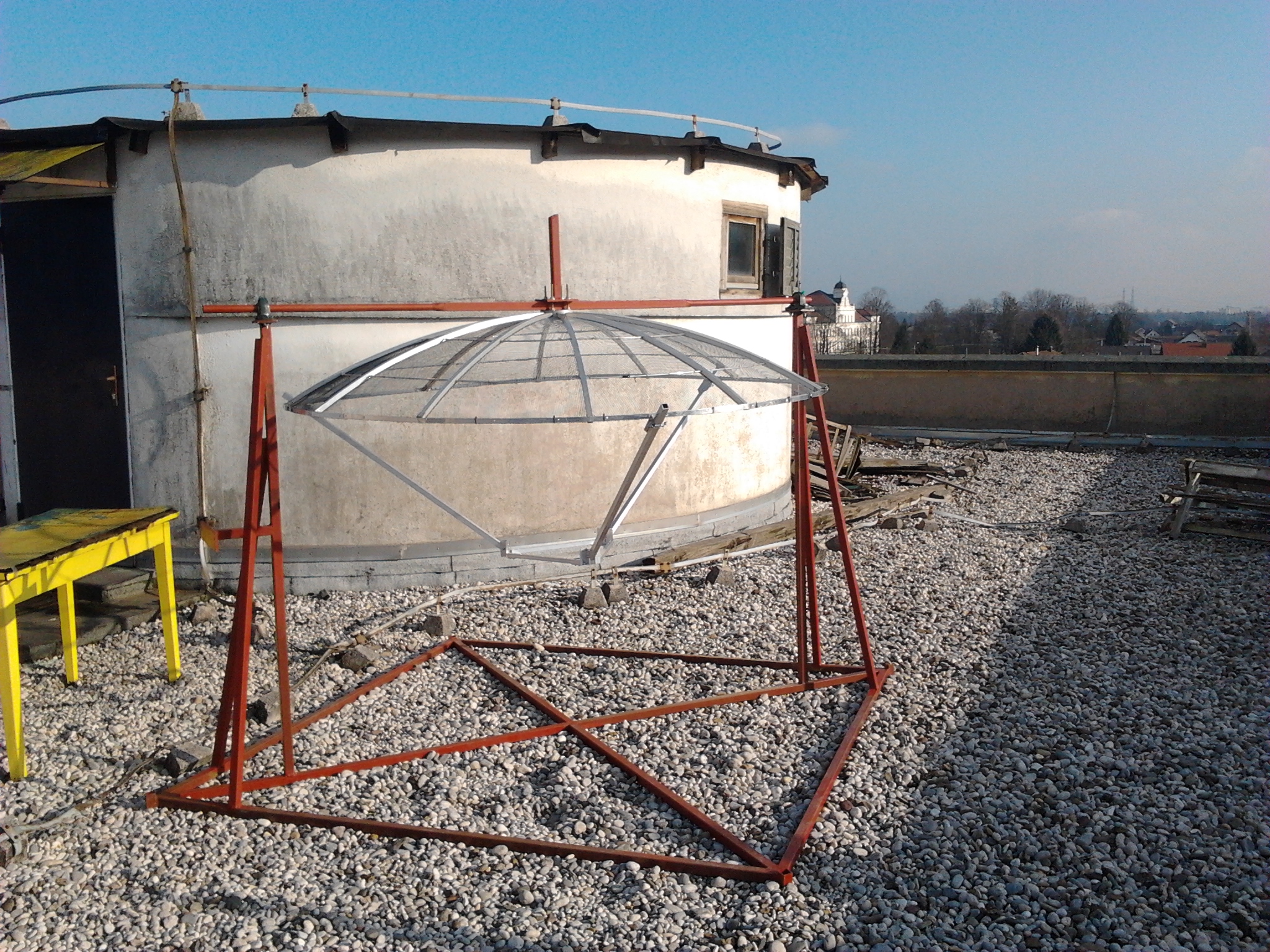
Antenna hanging freely on the stand. The missing parts are: the counterweight, the antenna feed, the axis motor and all of the electronics. The support structure for the feed can be clearly seen.
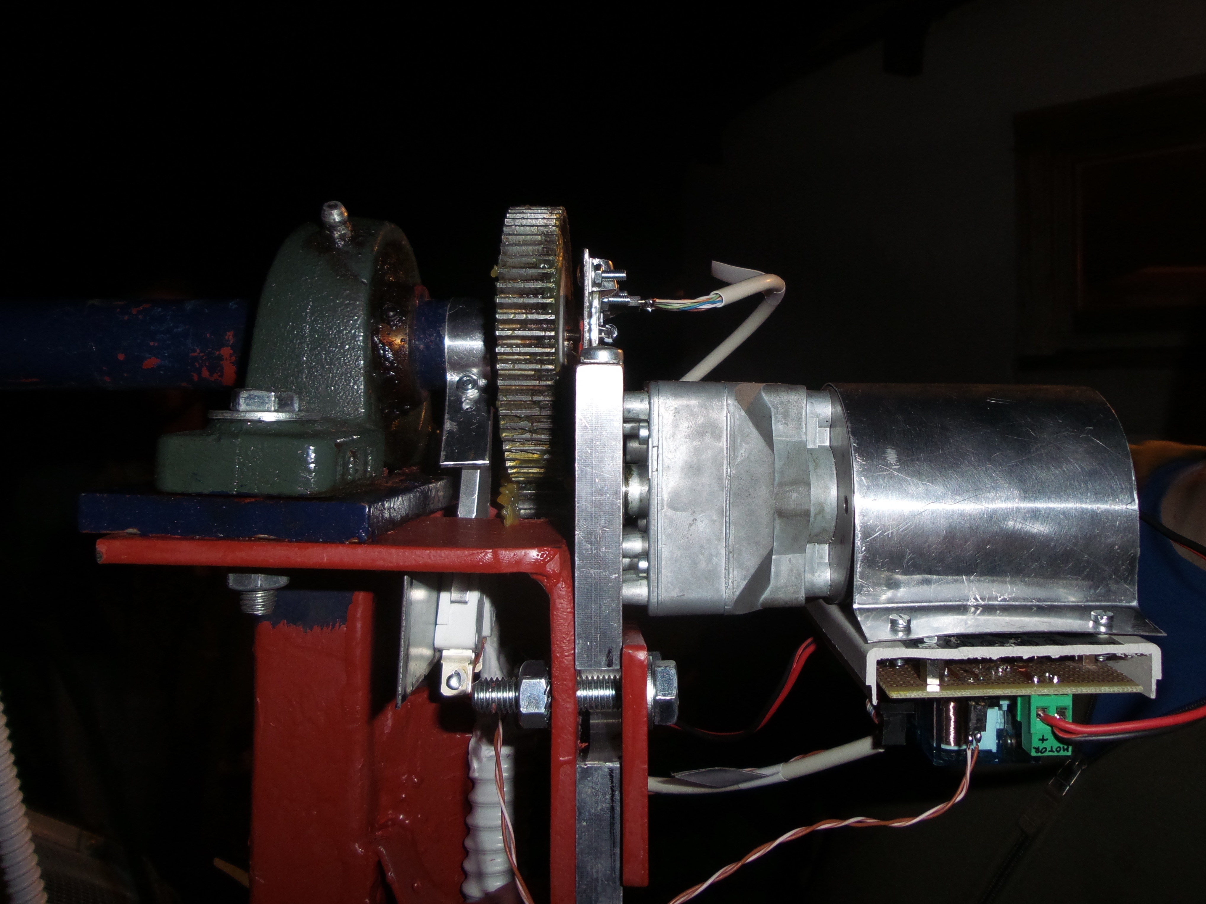
A side view of the motor and the transmission system for the elevation axis. The elevation sensor can be seen near the top.